Otto Construction
Public
Seaside, CA
$5,302,451
March 2018–August 2019
Education

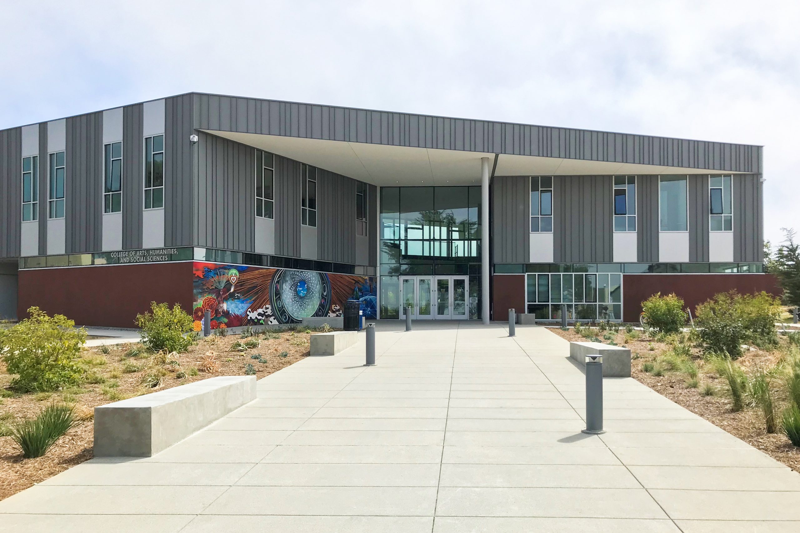
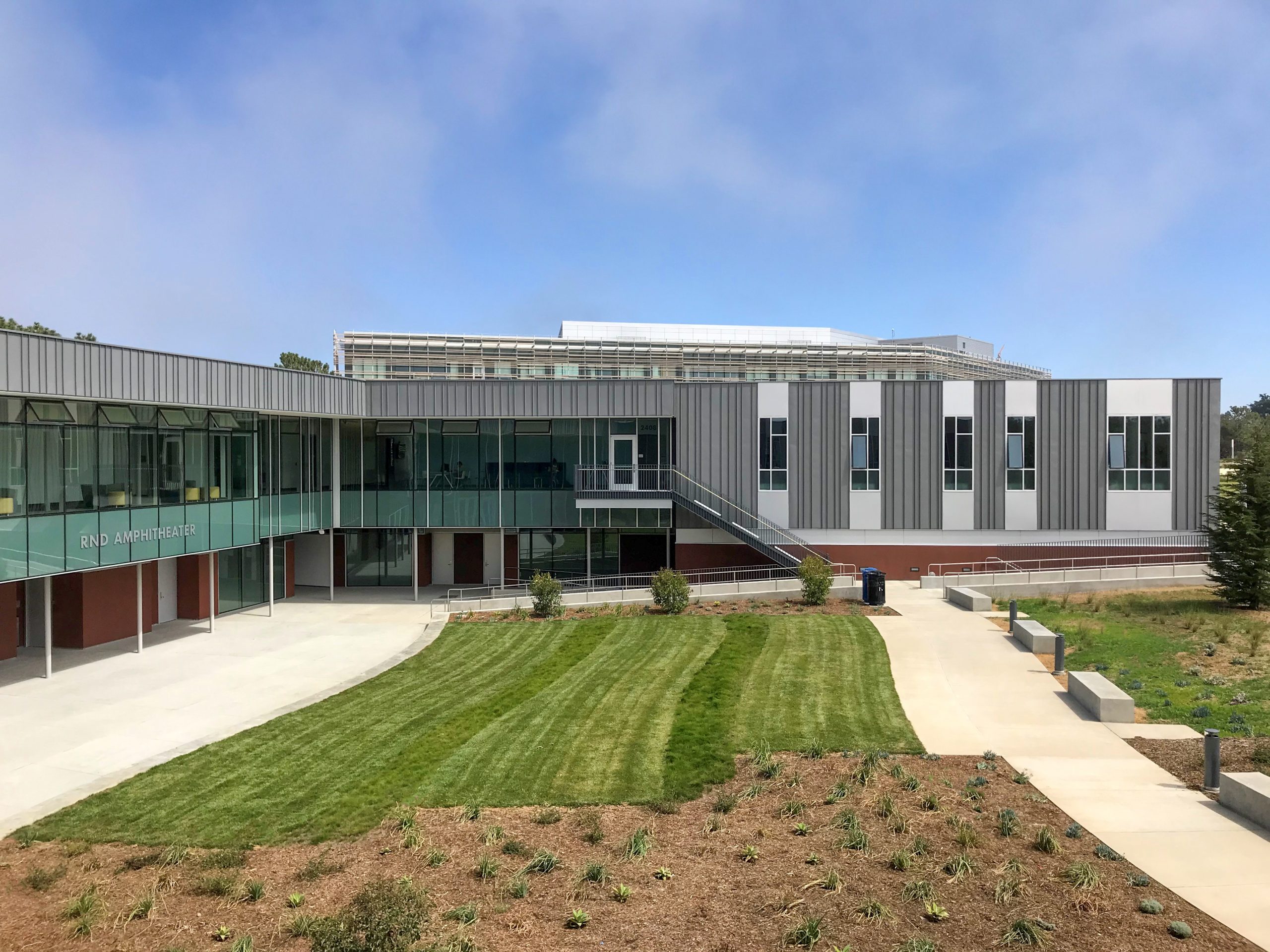
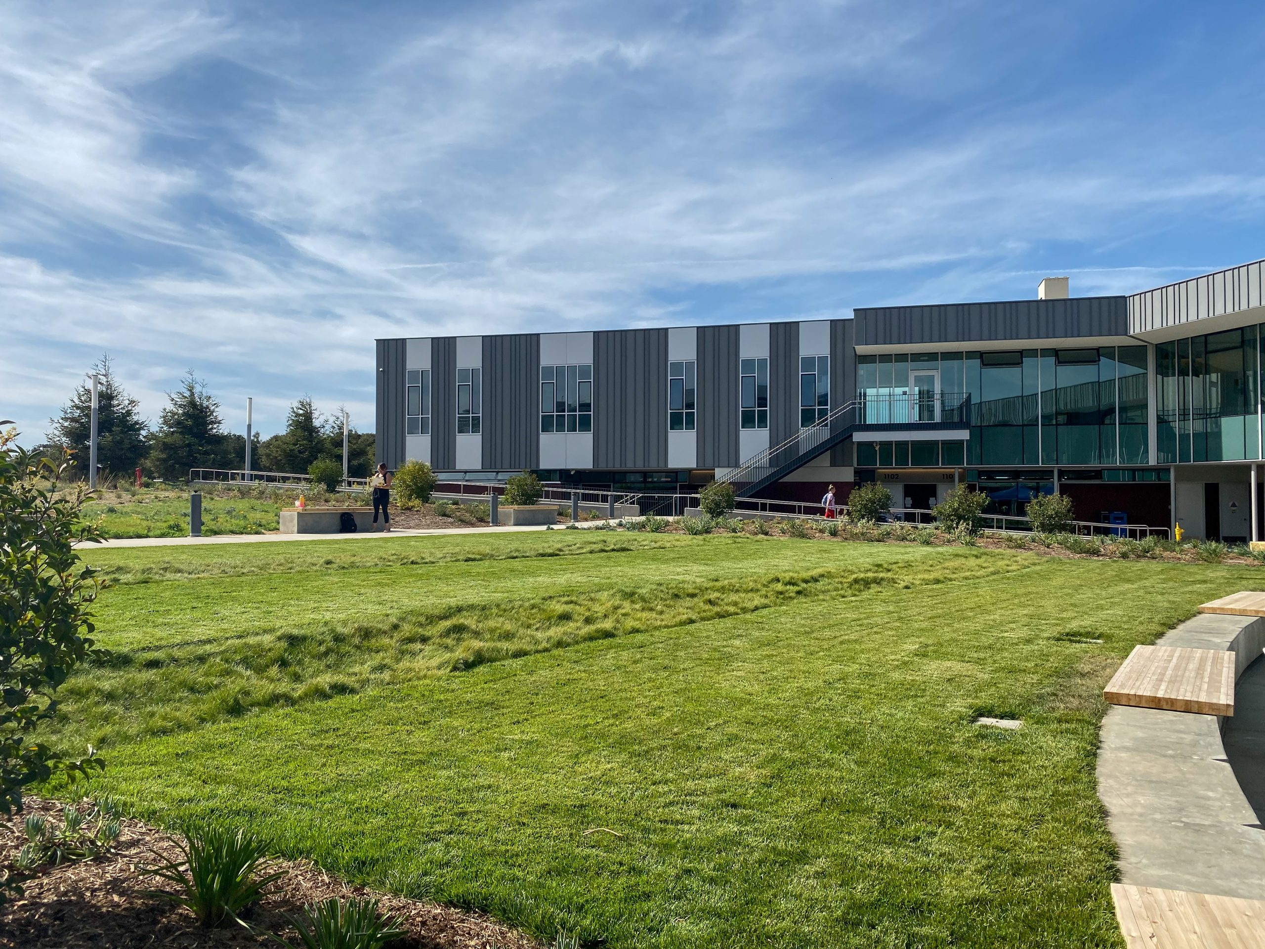
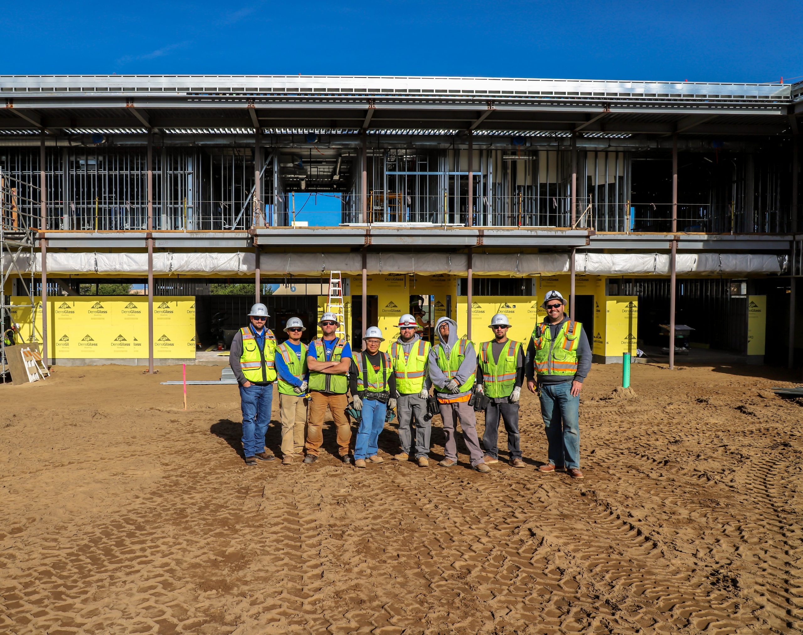
Years of planning and strategic growth culminated with Royal Electric’s successful completion of this innovative commercial project at California State University Monterey Bay in Seaside, CA. In coordination with the general contractor and other trades, Royal’s Preplanning and Logistics Department, the precursor to our Virtual Construction Design Team, was dedicated to ensuring that we hit the ground running once construction began. In addition to the preplanning, our field crews performed installations at an unparalleled pace, leading to the establishment of the Academic III Building project as a model for future design build work. We are proud to have delivered for the owner, CSU Monterey Bay, as they strive to transform what was once a key U.S. Army basic training facility into a premier learning and research center. Royal Electric Company not only played an impressive role in the advancement of this goal, but we also positioned ourselves at the forefront of a technological revolution.
The area in and around CSU Monterey Bay comprises a portion of the U.S. Army’s former base at Fort Ord. At its peak approximately 36,000 soldiers, federal employees and their families lived there. Over the course of 70 years roughly 1.5 million people completed basic training at the base with its ranges for hand grenades, rockets, rifles, and artillery. The facility’s closure in 1994 initiated an extensive process of cleaning up and transforming the area for new uses. What had started as a plan to develop a satellite campus for CSU San Jose materialized into a full-fledged state university, thanks in part to the efforts of Congressman Leon Panetta and support from other local and national stakeholders. Since the start of the first academic year in August of 1995 the campus has seen sustained growth. There are several projects currently underway and nearly 40 additional projects scheduled through 2035 according to a 2017 Master Plan.
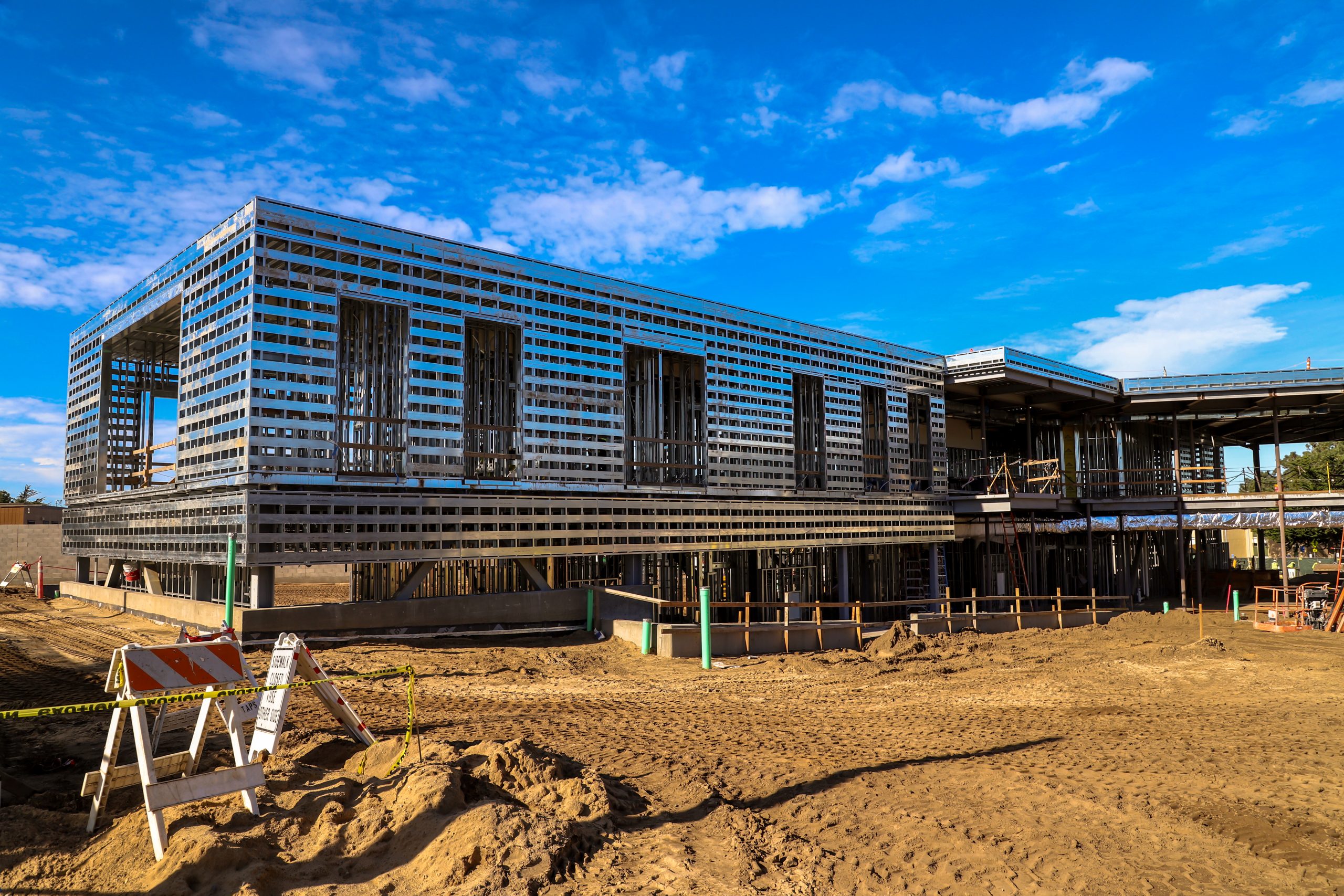
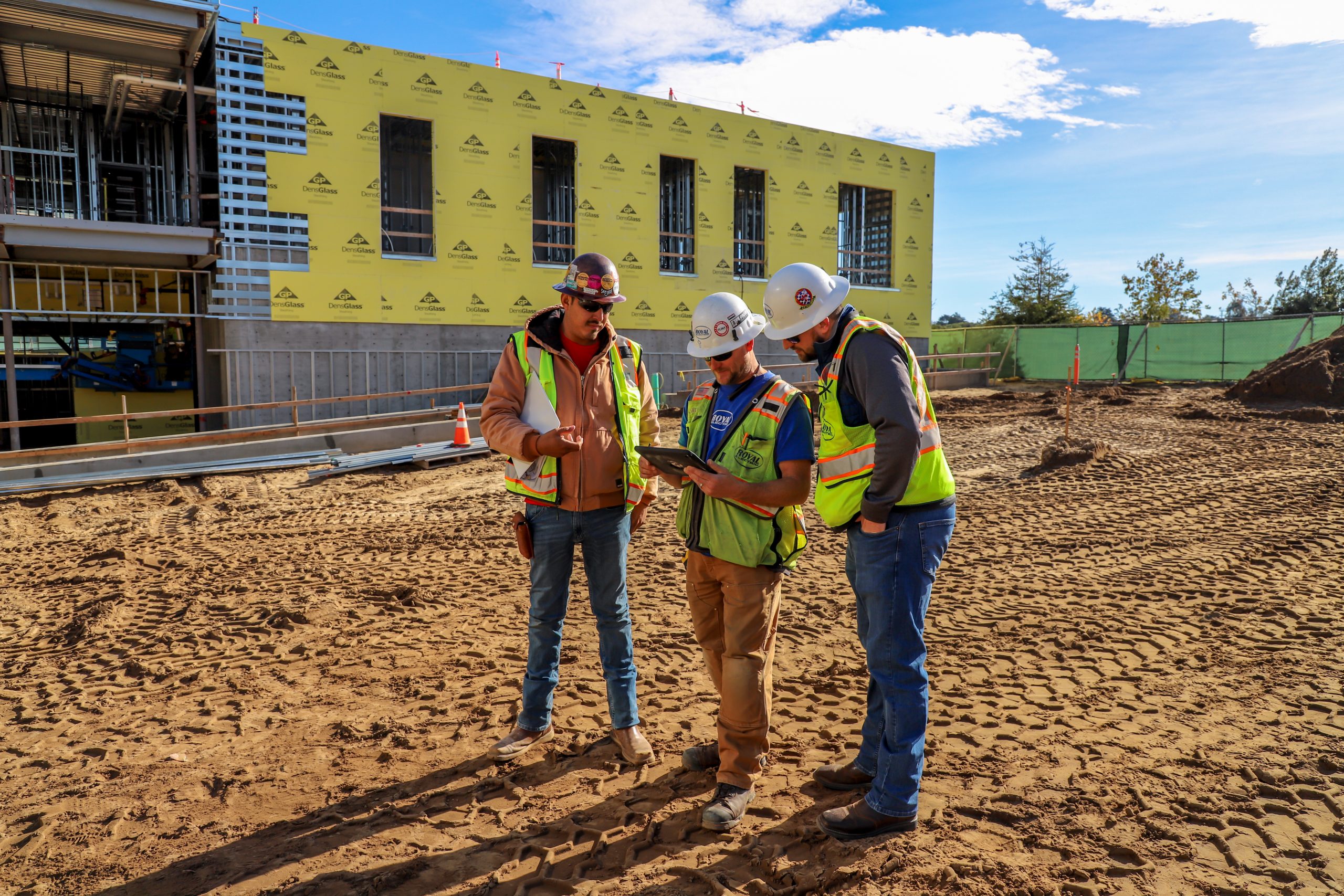
The Academic III Building project embodied a framework for future design build contracts, as it was one of the first that utilized state-of-the-art 3D building information modeling (BIM) software and laser mapping technology to ensure drawings were detailed as accurately as possible. Prefabrication technicians helped make the model a reality by sending a steady stream of materials to the jobsite. This involved intensive collaboration amongst our own teams as well as the general contractor and mechanical, plumbing, and fire sprinkler subcontractors. The design team planned out virtually every aspect of the building, allowing them to run clash detection on combined models over a three-month period. After uploading their electrical models our in-house BIM detailers took part in weekly online meetings with the project’s design team. This process resolved many issues associated with limited overhead space, such as when our two-inch electrical conduit clashed with a giant air duct or when the mechanical subcontractor’s diffusers clashed with our lighting locations. While at times the design process was challenging, the give and take set the project apart from conventional commercial builds which rely on established delivery methods.
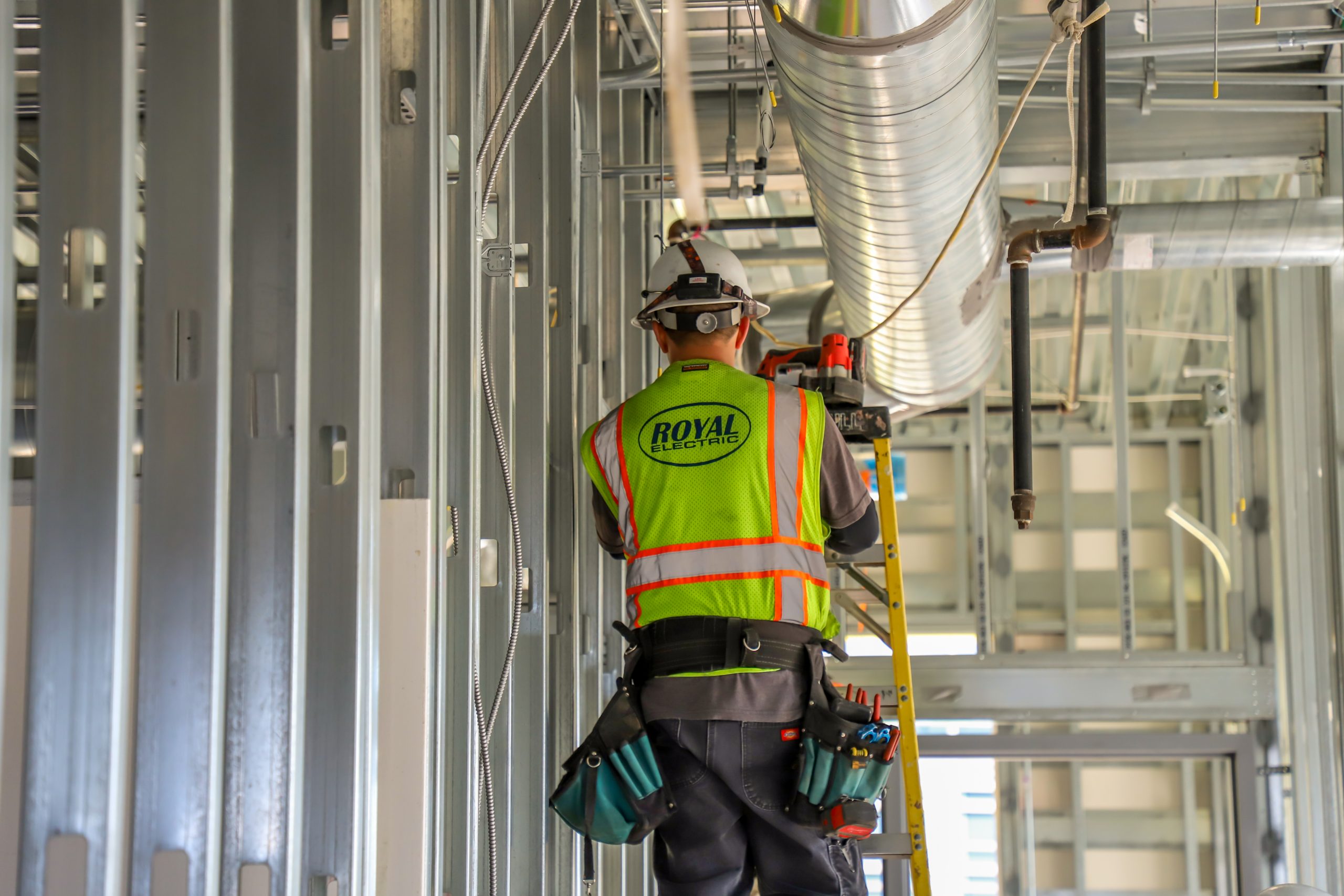
As the Academic III Building’s walls took shape in the 3D world, we moved on to detailing each individual room. This detailing included wire routing and circuit distribution, down to the count and length of wire. We also modeled the conduit and wire for homerun and pull boxes which fed the electrical devices in the rooms. Additionally, the specifications required data cables to be supported by a pathway of j-hooks run throughout the building. We collaborated with our low voltage subcontractor to mark up a pathway on the drawings which we established as a “no fly zone.” This space was reserved among everything else hung from the ceiling, including supports for the conduit racks, pull boxes, homerun cans, and lighting. While overhead lighting was previously designed, our team reviewed the type of each fixture as well as its location for quality control. With the coordinated model for the first level complete, it was utilized to layout the second-floor deck. Layouts included areas where an opening was needed in the floor to allow conduit to pass through, along with locations where receptacles or data outlets were installed in second level’s floor.
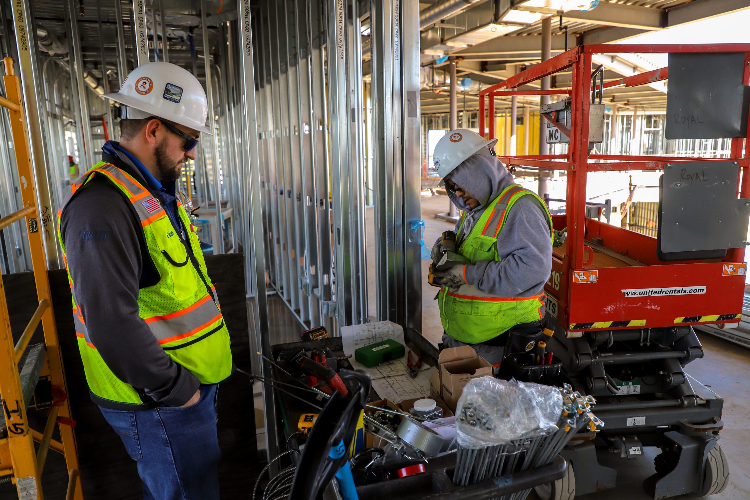
While the BIM team worked on the detailing Royal’s Preplanning and Logistics Manager, Carlos Dimas, simultaneously organized purchasing and prefabrication efforts. It was vital to begin sourcing materials early in order to maintain efficient lead times as detailers pushed to complete submittals and combine coordinated drawings. With the potential for confusion regarding complex specifications interruptions in materials’ purchasing and in turn prefabrication were a possibility. But our design team strived to mitigate miscommunications through effective RFI’s. The shop utilized a flattened 2D version of the coordinated 3D model to prefabricate as many materials as possible, assembling kits for field crews to install. These kits included materials for the in-wall and overhead rough-ins. Roughly 500 receptacles were pre-wired to outlet boxes, with clear construction covers to prevent damage and theft, along with the corresponding switches. Conduit data stubs were cut to length and pre-bent at a 45-degree angle for installation in the T-bar ceiling. Overhead lighting and occupancy sensors were also prefabricated and pre-wired to lighting junction boxes with fixture whips, creating a connection between the junction box and light fixture. Additionally, metal clad cable was cut to length for homerun cans. Later, the physical world met the digital as BIM detailers traveled to the project site to perfect field drawings.
Detailers loaded field drawings into a Trimble Robotic Total Station (RTS) with layout points throughout the jobsite. Precision lasers in the hardware allowed them to find the exact location of each point in the field, streamlining the work of operators and electricians. Some points were located directly over the center line of trenches and conduit stub ups, while others marked the position of everything installed within the concrete decks and the walls. This process meticulously identified details such as floor box infrastructure, sleeves, and blue bangers. Sleeves are holes in the deck for conduit to run through, while blue bangers are used to mount threaded rods for lighting to be hung overhead. The RTS identified hundreds of these layout points in a day which were later compiled on 8.5×11 inch sheets for field crews. They also included all other information necessary to complete the in-wall and ceiling rough-ins. With the drawings and rough-in kits provided, crews followed quickly behind detailers installing Blue Banger deck inserts for supports which would later be used to hang conduit, lighting and other devices.
Unexploded ordinance was a major concern during construction of the Academic III Building, which is on the grounds of a former parking lot.
Although the preplanning stage of the project was not exactly completed in a step by step process, it was roughly tackled from the ground up. Underground conduit details such as the number, size, purpose, routing, depth, and positioning were vital. Some of the information existed throughout different sets of drawings but in the end we needed to plan out much of it. Under-slab details on the other hand, involving conduit directly below the concrete situated on compacted sand and rock, were not included in the plans.
With most coordination issues resolved in the design phase, trenching and installations in the field not only progressed smoothly but also at a rapid pace. The sandy soil onsite proved challenging, although easier to dig through extensive shoring was required. The quick pace of construction took the project team by surprise resulting in sequencing challenges. Getting materials to the jobsite fast enough was difficult, meaning crews had to jump from room to room according to areas that were ready.
Special training was required for our crews in the event that they came across buried mortar or artillery rounds.
Collaboration with other trades was crucial in identifying where to safely stub conduit up through the deck and into the walls. With minimal space in the ceiling, clash detection was also vital for the overhead. Otto’s BIM Execution Plan required coordination for any rack supporting two or more conduit as well as any individual conduit two inches or larger. Details involved the height of the rack, along with the grouping, size, and amount of conduit on it.
Our electricians took these obstacles in stride and newly hired local crew worked exceptionally well together under the direction of Foreman and Employee of the Year, James Lewis. The steady flow of prefab kits meant that manpower issues typical of conventional projects were mitigated, making a small crew of roughly half a dozen electricians tremendously effective. At first the construction was challenging for the crew because the process was completely new to them. But after some manpower reshuffling and adjustments, the work became extremely productive and efficient thanks to the leadership of our foreman.